This page does not represent the most current semester of this course; it is present merely as an archive.
1 Overview
This assignment created 3D imagery using ray tracing instead of rasterization. In most other respects, its logistics are similar to the previous assignment.
1.1 Ray Emission
Rays will be generated from a point to pass through a grid in the scene. This corresponds to flat projection, the same kind that HW2’s frustum matrix achieved. Given an image \(w\) pixels wide and \(h\) pixels high, pixel \((x, y)\)’s ray will be based the following scalars:
\[s_x = {{2 x - w} \over {\max(w, h)}}\]
\[s_y = {{h - 2 y} \over {\max(w, h)}}\]
\(s_x\) and \(s_y\) correspond to where on the screen the pixel is: \(s_x\) is negative on the left, positive on the right; \(s_y\) is negative on the bottom, positive on the top. To turn these into rays we need some additional vectors:
eye
initially \((0, 0, 0)\). A point, and thus not normalized. forward
initially \((0, 0, -1)\). A vector, but not normalized: longer forward vectors make for a narrow field of view. right
initially \((1, 0, 0)\). A normalized vector. up
initially \((0, 1, 0)\). A normalized vector.
The ray for a given \((s_x, s_y)\) has origin eye and direction forward + \(s_x\)right + \(s_y\)up.
1.2 Ray Collision
Each ray will might collide with many objects. Each collision can be characterized as \(o + t \vec{d}\) for the ray’s origin point \(o\) and direction vector \(\vec{d}\) and a numeric distance \(t\). Use the collision with the smallest positive \(t\).
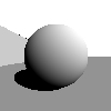
1.3 Illumination
Basic illumination uses Lambert’s law: Sum (object color) times (light color) times (normal dot direction to light) over all lights to find the color of the pixel.
Make all objects two-sided. That is, if the normal points away from the eye, invert it before doing lighting.
2 Required Features
The required part is worth 50%
png widthheightfilename
same syntax and semantics as previous assignments.
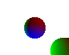
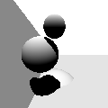
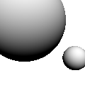
sphere \(x\)\(y\)\(z\)\(r\)
Add the sphere with center \((x, y, z)\) and radius \(r\) to the list of objects to be rendered. The sphere should use the current color as its color (also the current shininess, tecture, etc. if you add those optional parts).
For the required part you only need to be able to draw the outside surface of spheres.
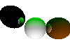
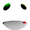
sun \(x\)\(y\)\(z\)
Add a sun light infinitely far away in the \((x, y, z)\) direction. That is the direction to light vector in the lighting equation is \((x, y, z)\) no matter where the object is.
Use the current color as the color of the sunlight.
For the required part you only need to be able to handle one light source.
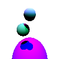
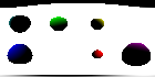
color \(r\)\(g\)\(b\)
Defines the current color to be \(r\)\(g\)\(b\), specified as floating-point values; \((0, 0, 0)\) is black, \((1, 1, 1)\) is white, \((1, 0.5, 0)\) is orange, etc. You only need to track one color at a time. If no color has been seen in the input file, use white.
You’ll probably need to map colors to bytes to set the image. All colors ≤ 0.0 should map to 0, all colors ≥ 1 should map to 255; map other numbers linearly (the exact rounding used is not important).
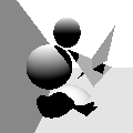
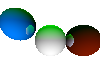
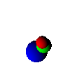
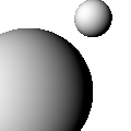
Overlap
Your rays should hit the closest object even if there are several overlaping.
3 Optional Features
3.1 Geometry (5–50%)
Handle interiors (requires bulb) (10%)
Correctly render when the camera is inside a sphere
plane \(A\)\(B\)\(C\)\(D\) (5%)
defines the plane that satisfies the equation \(Ax + By + Cz + D = 0\)
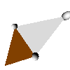
Triangle (requires plane) (15%)
Add xyz and trif commands, with the same meaning as in HW2 (except ray-traced, not rasterized).
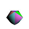
Interpolate triangles (requires triangle) (5–20%)
Triangles can have values interpolated in ray tracing using Barycentric coordinates. Examples of values to interpolate:
normal \(x\)\(y\)\(z\) (5%)
The same meaning as in HW2
trit \(i_1\)\(i_2\)\(i_3\) and texcoord \(s\)\(t\) (15%)
The same meaning as in HW2; see also Textures
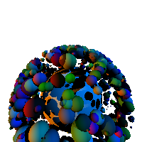
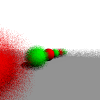
3.2 Acceleration (requires multiple suns and shadows) (30%)
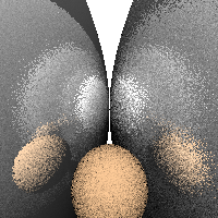
Add a spatial bounding hierarchy so that hi-res scenes with thousands of shapes can be rendered in reasonable time.
The basic idea of a bounding hierarchy is simple: have a few large bounding objects, each with pointers to all of the smaller objects they overlap. Only if the ray intersects the bounding object do you need to check any of the objects inside it.
For good performance, you’ll probably need a hierarchy of objects in a tree-like structure. In general, a real object might be pointed to from several bounding objects.
Rather than try to inspect your bounding hierarchy code, we’ll say you’ve achieved acceleration if you can render the scene shown here (which contains 1001 spheres, two suns, and shadows) in less than a second. And yes, this is arbitrary wall-clock time on our test server, and yes this does disadvantage people writing in Python (which is tens to hundreds of times slower than the other languages people are using in this class).
3.3 Lighting (5–50%)
Multiple suns (5%)
allow an unlimited number of sun commands; combine all of their contributions;
Add a point light source centered at \((x, y, z)\). Use the current color as the color of the bulb. Handle as many bulbs and suns as there are in the scene.
Include fall-off to bulb light: the intensity of the light that is \(d\) units away from the illuminated point is \(1 \over d^2\).
negative light (requires bulb) (5%)
Allow light colors to be less than zero, emitting darkness.
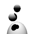
Shadows (10–30%)
No new commands for this one: you get these points if objects always cast shadows, you don’t if they don’t.
10 points for 1 sun, +5 if planes work, +5 if triangles work, +5 if multiple light sources work, +5 if bulbs work
3.4 Materials (5–65%)
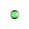
shininess \(s\) (10%)
Future objects have a reflectivity of \(s\), which will always be a number between 0 and 1.
If you implement transparency and shininess, shininess takes precident; that is, shininess 0.6 and transparency 0.2 combine to make an object \(0.6\) shiny, \(((1-0.6) \times 0.2) = 0.08\) transparent, and \(((1-0.6) \times (1-0.2)) = 0.32\) diffuse.
Per page 153 of the glsl spec, the reflected ray’s direction is
\[\vec{I} - 2(\vec{N} \cdot \vec{I})\vec{N}\]
… where \(\vec{I}\) is the incident vector, \(\vec{N}\) the unit-length surface normal.
Bounce ech ray a maximum of 4 times unless you also implement bounces.
shininess \(s_r\)\(s_g\)\(s_b\) (5%)
Future objects have a different reflectivity for each of the three color channels.
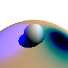
transparency \(t\) (requires shininess) (15%)
Future objects have a transparency of \(t\), which will always be a number between 0 and 1.
Per page 153 of the glsl spec, the refracted ray’s direction is
… where \(\vec{I}\) is the incident vector, \(\vec{N}\) the unit-length surface normal, and \(\eta\) is the index of refraction. If \(k\) is less than 0 then we have total internal reflection: use the reflection ray described in shininess instead.
Use index of refraction 1.458 unless you also implement ior. Bounce ech ray a maximum of 4 times unless you also implement bounces.
transparency \(t_r\)\(t_g\)\(t_b\) (5%)
Future objects have a different transparency for each of the three color channels.
ior \(r\) (requires transparency) (5%)
Set the index of refraction for future objects. If ior has not been seen (or if you do not implement ior), use the index of refraction of pure glass, which is 1.458.
bounces \(d\) (requires shininess) (5%)
When bouncing rays off of shiny and through transparent materials, stop generating new rays after the \(d\)th ray. If bounces has not been seen (or if you do not implement bounces), use 4 bounces.
roughness \(\sigma\) (requires shininess) (10%)
If an object’s roughness is greater than 0, randomly perturbed all three components of the surface normal by a gaussian distribution having standard deviation of \(\sigma\) (and then re-normalize) prior to performing illumination, refaction, or reflection.
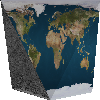
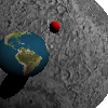
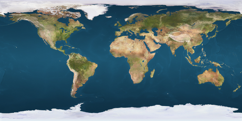
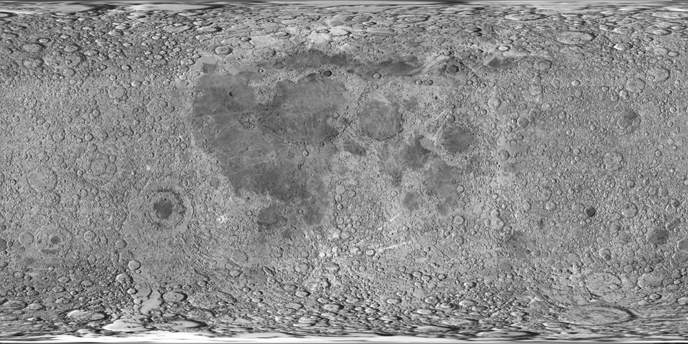
Textures (10%)
This involves at least one command (for spheres) and possibly a second (for triangles, if used)
texture filename.png
load a texture map to be used for all future objects. If filename.png does not exist, instead disable texture mapping for future objects.
The texture coordinate used for a sphere should use latitude-longitude style coordinates. In particular, map the point at
the maximal \(y\) to the top row of the texture image,
the minimal \(y\) to the bottom row,
the maximual \(x\) to the center of the image,
the minimal \(x\) to center of the left and right edges of the image (which wraps in x),
the maximal \(z\) to the point centered top-to-bottom and 75% to the right, and
the minimal \(z\) to the point centered top-to-bottom and 25% to the right.
The standard math library routine atan2 is likely to help in computing these coordinates.
See also Interpolate triangles for the texcoord and trit commands.
3.5 Sampling (5–65%)
eye \(e_x\)\(e_y\)\(e_z\) (5%)
change the eye location used in generating rays
forward \(f_x\)\(f_y\)\(f_z\) (10%)
change the forward direction used in generating rays. Then change the up and right vectors to be perpendicular to the new forward. Keep up as close to the original up as possible.
The usual way to make a movable vector \(\vec{m}\) perpendicular to a fixed vector \(\vec{f}\) is to find a vector perpendicualr to both (\(\vec{p} = \vec{f} \times \vec{m}\)) and then change the movable vector to be perpendicular to the fixed vector and this new vector (\(\vec{m}\prime = \vec{p} \times \vec{f}\)).
up \(u_x\)\(u_y\)\(u_z\) (requires forward) (5%)
change the up direction used in generating rays. Don’t use the provided up directly; instead use the closest possible up that is perpendicular to the existing forward. Then change the right vector to be perpendicular to forward and up.
aa \(n\) (15%)
shoot \(n\) rays per pixel and average them to create the pixel color
fisheye (10%)
find the ray of each pixel differently; in particular,
divide \(s_x\) and \(s_y\) by the length of forward, and thereafter use a normalized forward vector for this computation.
let \(r^2 = {s_x}^2 + {s_y}^2\)
if \(r > 1\) then don’t shoot any rays
otherwise, use \(s_x\)right, \(s_y\)up, and \(\sqrt{1-r^2}\)forward.
panorama (10%)
find the ray of each pixel differently; in particular, treat the x and y coordinates as latitude and longitude, scaled so all latitudes and longitudes are represented. Keep forward in the center of the screen.
dof \(focus\)\(lens\) (requires aa) (10%)
simulate depth-of-field with the given focal depth and lens size. Instead of the ray you would normally shoot from a given pixel, shoot a different ray that intersects with the standard ray at distance \(focus\) but has its origin moved randomly to a different location within \(lens \over 2\) of the standard ray origin. Keep the ray origin within the camera plane (that is, add multiples of the right and up vectors but not forward.
If you do dof and fisheye or panorama, you do not need to implement dof for those alternative projections.
 Add the sphere with center \((x, y, z)\) and radius \(r\) to the list of objects to be rendered. The sphere should use the current color as its color (also the current shininess, tecture, etc. if you add those optional parts).
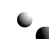 Add a sun light infinitely far away in the \((x, y, z)\) direction. That is the
 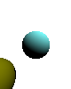 Defines the current color to be \(r\) \(g\) \(b\), specified as floating-point values; \((0, 0, 0)\) is black, \((1, 1, 1)\) is white, \((1, 0.5, 0)\) is orange, etc. You only need to track one color at a time. If no
 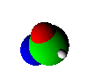 Your rays should hit the closest object even if there are several overlaping.


