Lab 3 - Circuits
In this lab, we’ll get more familiar with combining the logic gates we experienced in class and the reading into more complicated circuits that can do multi-bit calculation. Rather than drawing these circuits on paper, we’ll use an online circuit simulator to see them in action.
Lab Goals
After this lab, you should:
- Understand how to combine logic gates to produce multi-bit operations such as
- The ripple-carry adder
- A subtractor
- Be able to picture how these circuits produce the results of our multi-bit operations
Getting Started
We will be using the online electronic circuit simulator, which we used to visualize the D flip-flop circuit (i.e., the 1-bit register) at http://www.falstad.com/circuit/e-edgedff.html.
First, open up a new circuit diagram. You may either open the register above or go directly to the simulator at http://www.falstad.com/circuit/circuitjs.html. From there, choose File and New Blank Circuit from the menu. This will clear the current example circuit and provide you with a blank workspace in which to create.
I would encourage clicking the RUN / Stop button so that the simulator does not begin counting time. However, when you are ready to view your circuit in action, you will want to start the simulator again.
You may also wish to open the simulator full screen, by choosing File and Toggle Full Screen. Additionally, scrolling on the workspace will zoom in and out.
The simulator provides all the logic gates we have discussed in the class so far, along with many other components. For the purpose of this lab, we will only be using the following, available under the Draw menu:
- Wire (w)
- Logic Gates, Input and Output (submenu)
- Logic Input (i)
- Logic Output (o)
- Inverter, which is our not gate (1)
- AND Gate (2)
- OR Gate (3)
- XOR Gate (4)
Note: For this lab, you should not need to use the NAND or NOR gates, but you are welcome to use them.
Practice drawing a few gates first. Choose the gate from the Draw menu, or press the corresponding key (in parentheses above), then click and drag to the right to draw the gate and associated input/output wires. Gates may be moved by holding the shift key and clicking/dragging. Connect the output of one gate to the input of another by using the Wire (w) to make the connection.
Once you have an example circuit connected, we need to add inputs to affect the state of our circuit. Drawing a Logic Input (i) connected to any of our gates’ wires will display either an H (for high voltage, or 1) or L (for low voltage, or 0). When the simulator is running, i.e., RUN is bolded in the RUN/Stop button, then clicking on the input value (H or L) will toggle the input. Notably, wires representing 1s in our circuit (high voltage) will be highlighted in green to help us visualize the inner workings of the circuit. Adding a Logic Output (o) will provide a similar H/L display that automatically updates to the current value present on the wire.
Below, we can see a simple circuit with 3 inputs and 1 output. The top two inputs (one 1 and one 0) are connected to an XOR gate. Since 1 ^ 0 = 1, we see that result is connected to the first input to the ADD gate. Our third input (1) is connected directly to the AND gate as its second input. Lastly, we see that the result of the AND is connected to an out put which reads H (or 1).
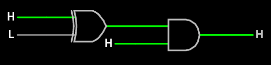
Example Circuit
Once you have become familiar with the simulator interface, it is time to try out some of our circuits from class.
Experimenting with Circuits
For the rest of lab, we’ll ask you to load, modify, or draw some circuits and then test them with a few inputs. The goal here is to understand more fully how the logic gates in our circuits combine to produce the answers we expect, so we will be asking you to experiment with them rather than directly calculate the final results as we might have with Homework 1.
Ripple Carry Adder
Begin by loading the 4-bit Ripple Carry Adder that computes z = x + y, as discussed in the Fancier Logic reading and in class. Download ripple-carry-adder.circuitjs.txt, then choose File and Open File in the simulator. It should draw the ripple carry adder as seen below.
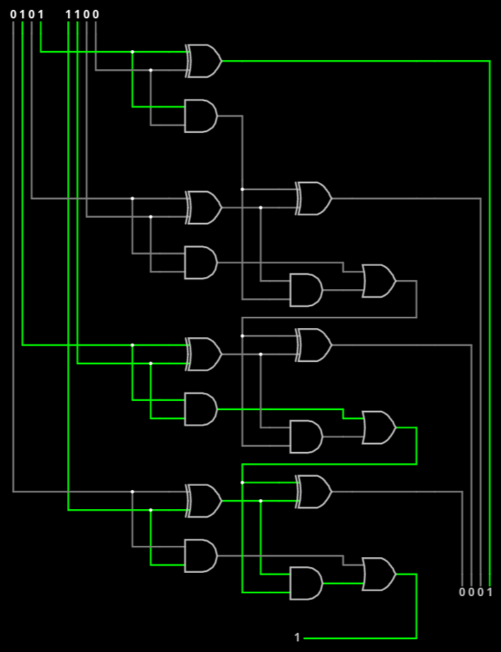
Ripple Carry Adder in Simulator adding 5 + 12 with overflow (or 5 + -4 in two’s complement)
We have collected the input wires in the upper left (4 bits for x and 4 bits for y), and the four output wires in the bottom right (4 bits for z). At the very bottom, you’ll notice the carry bit, which does not form part of the output for z. Clicking on an input bit’s value will change its value from 0 to 1 when the simulator is running.
Run the simulation and add the following numbers (given in decimal):
- 0 + 1
- 1 + 1
- 2 + 2
- 10 + 5
- 15 + 1
- 15 + 15
Note the output in each case and how any overflow is (or is not) handled in the circuit.
Now modify the adder to add 5-bit numbers instead. *Hint, if “Select/Drag Set” is selected in the draw menu, you may select a portion of the circuit to copy/paste as needed.”
Run the simulation again and add the following numbers (given in decimal):
- 0 + 1
- 15 + 1
- 16 + 15
- 31 + 1
- 31 + 31
Save your circuit by using the File, Save As menu. Do not share this with others outside your lab group, but save a copy to check off with your TA.
Ripple Carry Subtractor
Now, modify your adder to produce a subtractor instead. Since your adder originally calculated z = x + y, it should now produce z = x - y. Brainstorm some different ideas converting your adder into a subtractor.
- What is the fewest number of gates you need to add in order to produce a subtractor?
- You may want to “pre-process” one of your 5-bit inputs
- You may need an additional input bit
Once you have created your subtractor, run your simulation and subtract the following numbers (given in decimal):
- 15 - 0
- 15 - 1
- 31 - 31
- 22 - 6
- 22 - 3
- 6 - 19
- 0 - 1
Note the output in each case and what happens when the result would be negative. How does this help us with Two’s Complement? (Remember that 11111 is -1 in 5-bit Two’s Complement.)
Save your circuit by using the File, Save As menu. Do not share this with others outside your lab group, but save a copy to check off with your TA.
Towards a Computer
Next we will create a new circuit.
In class, we have been working towards building a computer that we can program with instructions. We created circuits to handle the work, on Wednesday, we’ll add a mux to choose the resulting value we wanted to store and a register to store the value for the next calculation.
For the rest of lab today, we will build a simplified version to visualize how the circuits will work. In this simplified version, we will define 4-bit instructions [CCAB] as follows:
- The first two bits (CC) will be the instruction code (that is, the “icode”) that determines what operation we will compute
- The third (A) and fourth (B) bits will be the two input values1
Our simplified circuit will compute a different operation, depending on which icode we provide, and output its result as follows:
| icode | operation |
|---|---|
0 | a AND b |
1 | a OR b |
2 | a XOR b |
3 | NOT a |
In our circuit, these 4-bit instructions enter as 4 separate 1-bit inputs, just as the inputs for x and y did in the ripple carry adder above. For example, if our instruction was 0110, the icode bits are 01 and the operands are 1 and 0; therefore, our circuit would output the result of 1 OR 0, which is 11. We will build this circuit in 2 parts: one part that handles the icode and another that handles the calculations.
Handling the icodes
To choose which operation’s value to output, we will use a multiplexer (mux). Note that we have 4 icode values, so we must construct a 4-input mux, which requires a 2-bit choice value. Build this mux on the right-hand side of the simulator window. Hint: since we have 2 bits of choice (i.e., two input wires), we can treat the high-order bit and low-order bit separately. Consider that 0 and 2 both have low order bit 0 and 1 and 3 both have low order bit 1. One approach is to use two 2-input muxes2 to distinguish between icodes 0 and 1 (using low-order bit) and 2 and 3 (using low-order bit) and then a third 2-input mux to distinguish between the higher order bits.
Once completed, you should have 4 wires ready for inputs to be connected to your mux, the final Logic Output connected to the output of your mux, and the first two Logic Inputs of our instruction (the first two input bits) used as the choice.
Performing the operations
Next, we must calculate the operations. We will always calculate all 4 operations; our mux will determine which operation is ultimately output3.
- Draw gates for each of the 4 operations, connecting their output to the respective input of the 4-input mux.
- Draw 2 Logic Inputs that will serve as the last two bits of our 4-bit instruction. Connect them to each logic gate in the previous step, as appropriate.
Testing your circuit
Once you have completed your circuit, try out a few different instructions:
0001- This should AND 0 and 1 (outputting 0)0110- This should OR 1 and 0 (outputting 1)1011- This should XOR 1 and 1 (outputting 0)1101- This should NOT 0 (outputting 1)
Save your circuit by using the File, Save As menu. Do not share this with others outside your lab group, but save a copy to check off with your TA.
Check-off with a TA
To check-off this lab, show a TA
- Your 5-bit ripple carry adder displaying the result of
28 + 3 - Your 5-bit subtractor displaying the result of
15 - 19 - Your multi-purpose circuit with the instructions
1010,1110, and0100
-
Note: this is different from our instructions in class to make designing the circuit in the simulator easier. In class, the two operands will tell us from which register to read (or write) the value. ↩ ↩2
-
You can find a drawing of a 2-input mux in the Components reading on Operators. ↩
-
In class, this output would be routed to the register file to be saved as needed and used in a future calculation. In our simplified circuit, we are not asking you to draw the register. If you wanted to experiment with it after class, the 1-bit D flip-flop register shown in class is available in the Circuits->Sequential Logic->Flip-Flops menu as the Edge-Triggered D Flip-Flop. (Selecting the circuit will replace your current drawing, but you may then select and copy, then undo and paste to add it to your drawing.) ↩